
The datasheet looks great, the sales pitch was dazzling and even with the working knowledge from earlier posts about how to determine the actual range, the sensor seems to meet all your requirements on paper.
Or does it? There are a couple of behaviors of Lidar sensors that are not well understood, not even by people who manufacture them. This post will cover one of those.
Divergence
This is not a post about the popular book series set in a post-apocalyptic dystopian society. This is a post about something much more exiting than that: The effects of laser beam divergence on shapes of detected objects. This is a much overlooked phenomenon in the Lidar detection world. Many datasheets don't even mention this value even though it has significant effects and is a major contributor to the maximum tracking and classification range a Lidar based perception system can reach.
What is divergence?
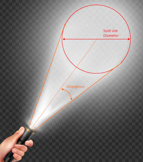
"In electromagnetics, especially in optics, beam divergence is an angular measure of the increase in beam diameter or radius with distance from the optical aperture or antenna aperture from which the beam emerges."
Or in normal English: "The further from the laser, the wider the beam."
Anyone who has ever held a flashlight has experienced beam divergence. You point a flashlight at a wall and walk towards it and the size of the brightest light spot on the wall gets smaller the closer you get.
"Designed by microvector/Freepik"
What many people do not know is that the same applies to laser pointers. In a quick experiment I took a laser pointer about one meter from a wall and then compared it with the same pointer about seven meters from the same wall. Below are the two spot sizes.
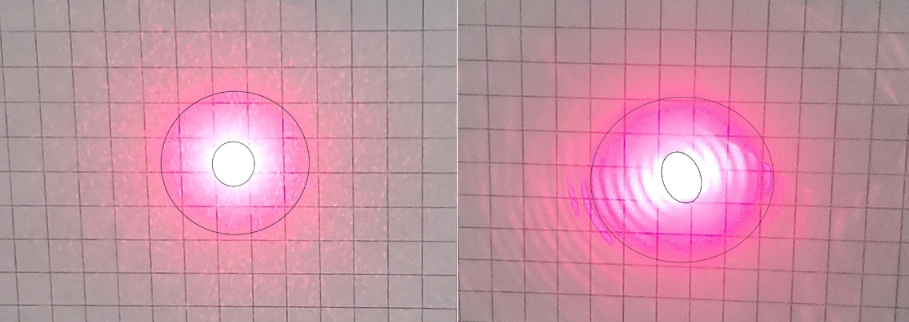
Now, for this experiment, I did not have access to a lab-grade laser, but just a cheap laser pointer you can buy off Amazon with some clear lens aberrations shown in the image on the right. The camera has trouble capturing the true spot size because it does not have enough HDR capability.
Hopefully, it still gets the point across that, even with a laser, the difference in spot size can be significant between 1 and just 7 meters. I measured this to be an increase of 30%. Now imagine the spot size at 100 meters and beyond, ranges at which Lidar are attempting to operate in.
A laser of this quality creates a spot size of 8mm at about 8m distance. This roughly translates to a divergence of 0.5 degrees. Most Lidar claim a divergence of between 0.1 and 0.5 degrees FWHM (Full Width at Half Maximum), though most manufacturers do not list this on their datasheets.
I will spare you the details of what 'Full Width at Half Maximum" means and how the Gaussian energy curve affects things exactly. Just know that advanced Lidar simulations have predicted the effects I am about to describe below and practical experiments have backed up the predictions that the simulator made.
What effect does spot size have in the Lidar world?
In short: a lot. It can skew things, smudge things, create bloom effects and make objects appear larger than they really are.
Let's start with a basic setup to explain the effect of divergence.
Here we have a Lidar emitted light pulse travelling towards a wall. In this first instance, the wall is perfectly perpendicular to the direction of the beam.
Underneath the pulse is a graph of the return energy detected by the sensor. For simplicity, I will be ignoring the delay of the signal to travel all the way back to the sensor as it has no impact on this specific case.
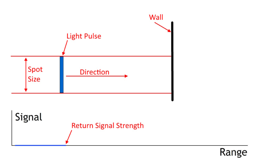
Now watch as the light pulse travels and hits the wall. Notice how the return signal changes:
In the above example there is a clear and sharp peak in the signal. With some form of peak-detection algorithm, the sensor will calculate the 'center' of the peak and that is the range that the Lidar sensor will use and send to the perception system. In the above example, the calculated range lines up very well with the actual range. In fact, increased spot size would have no effect on the calculated range.
Now we angle the wall:
Because of the angle, the return peak becomes wider. Still, the peak detection algorithm is able to determine the center of the peak and, as you can see, it lines up nicely with the center of the spot size.
Let's look at a corner of a wall and see how it behaves:
Hold on, the range the sensor calculated does not match up with the corner of the wall, instead it seems to 'hover' in front of it! This is exactly what divergence does: it smooths out corners and smudges objects.
Without showing the animation, imagine what the effect would be if the corner is flipped and the walls angle away from the sensor.
If you guessed that the detected range would be beyond the actual corner, you would be correct. Divergence works with corners in both directions.
Now also imaging making the spot size wider and try to predict the range as it relates to the spot size.
If you guessed that the range moves away from the corner as the spot size gets bigger, you would be correct.
To show that this is not just theoretical, here is a comparison of two actual Lidar units. This is a top down view of a room with two different Lidar units in an identical location covering the corner of my office.
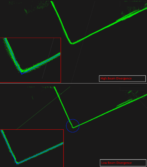
The top image creates a distinctive curve at the corner of a wall. The bottom Lidar has a much tighter curve, but what is more important is that the bottom Lidar is able to detect the little bump to the left of the corner (in the blue circle). That is actually the door frame. The top Lidar cannot detect it at all because it is too smudged to be able to tell.
What is most interesting about this? The top Lidar is more expensive and has much higher resolution than the bottom Lidar. On paper the top Lidar beats the bottom one in every listed category, but in practice, the bottom Lidar significantly outperforms the top Lidar in perception and the ability to make actual decisions based on the data.
The full (exaggerated) effect on a square object will look something like this. The below diagram shows a very standard Lidar setup. The purple dots are the resulting point cloud.
Note: The dotted lines indicate the total vertical field of view, not the divergence per beam.
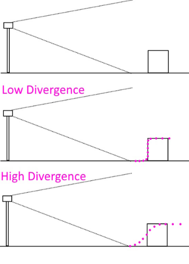
Not only is the bottom object smudged, it also appears larger and may blend in with objects around it. I will explain this phenomenon in a separate post as this one is getting pretty long already.
The below image shows the relationship between resolution and divergence:
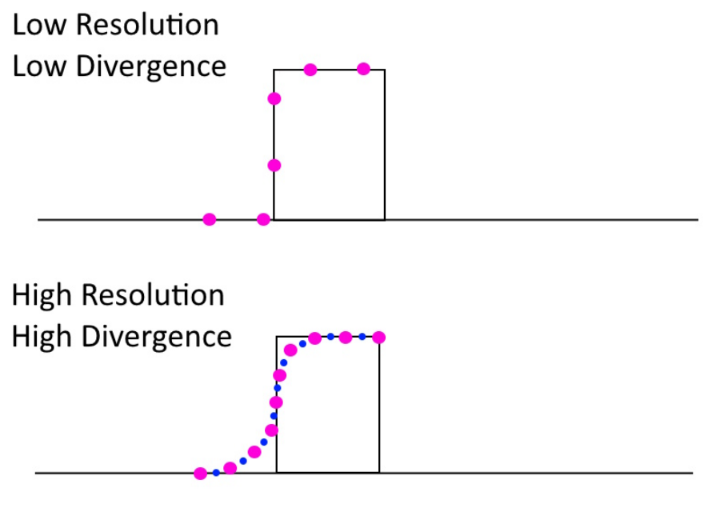
The bottom image has twice the resolution (purple dots). Does it have an advantage over the top image? What if we double the resolution again (blue dots), does it add any actual useful information?
No, it does not. Imagine the above situation but with a camera. You have an 8K camera, but the pixels bleed into each other. What's the point of having 8K? You're just wasting bandwidth.
This hopefully illustrates why more resolution is not always better. More resolution is only better if the rest of the sensor specs can back it up. If the horizontal angular resolution of a Lidar is 0.10 degrees and the divergence is 0.2 degrees, then what's the point?
I have always told all my customers: "I'd rather have 16 good beams than 100 bad ones."
So, when selecting a sensor, see the whole picture. Look past the datasheet and at the actual quality of the unit. The above scenarios are very basic tests that anyone can perform while you are evaluating sensors.
In a future article I will cover additional things to consider like temperature, vibration, reliability, lifecycle, blooming, 'streaming points'.
